


Flexible and versatile: Computer-aided design and manufacturing (CAD/CAM)
Author: Federico Presicci, DT, Steger Dental Laboratory, Brunico, Italy
There is one thing that everyday objects and utensils have in common with products that have to meet stringent technical or medical requirements. If they were designed digitally, it is possible to produce multiple copies over and over again – even from different materials.
In the dental field, the fabrication of custom-dimensioned and stable restorations using a CAD/CAM milling unit has become an established procedure. It is important, however, to use the correct parameters for the material used, such as wall thickness, width of the cementation gap, connector diameter, sintering shrinkage, sintering support for distortion-free sintering — and more.
If the design software used provides default settings that allow these parameters to be quickly adjusted to the particular material used and to the type of restoration (crown, bridge, splint, inlay, bar…), it is easy to be versatile and flexible in terms of the choice of material.
Case report: Computer-aided design options for complex rehabilitations
The patient, male, with partial dentition, suffered from periodontitis and lack of bone support (Fig. 1). Following extraction of all maxillary natural teeth, the patient received immediate implants (Adin) at sites 16, 13, 12, 22, 24 and 26 and an occlusal screw full-arch resin provisional (Fig. 2). The existing partial denture in the mandible was to remain in place for the time being, to be replaced with a fixed rehabilitation at a later date. The first task therefore had to be the provision of an aesthetic and functional maxillary restoration with long-term stability.
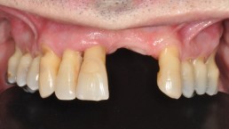
Figure 1: Maxillary situation prior to the extraction of all natural teeth.
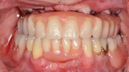
Figure 2: After the extractions, the patient received immediate implants (Adin) and a resin provisional.
The attending clinician – Fernando Rojas-Vizcaya, DDS, MS (Mediterranean Prosthodontic Institute, Castellón, Spain) – had developed a treatment plan that provided for a maxillary rehabilitation with a occlusally screw-retained 12-unit Prettau® Bridge, which he commissioned from our dental laboratory.
As a basis for creating the restoration we received articulated casts (master cast with laboratory analogues and gingival mask and cast of the opposing jaw) representing the patient situation. The casts were scanned four times for the CAD design step, and the image data sets resulting from the scans were matched (Figs. 3 – 5).
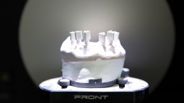
Figure 3: The scans provided the baseline data for the CAD design of the final restoration. The scanner also acquired the exact spatial orientations of the implants within the jaw by scanning the Scanmarkers that had been screwed into the laboratory analogues on the cast.
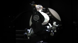
Figure 4: Digital data on the occlusion and centric relation were derived from the scans of the articulated casts.
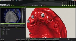
Figure 5: The scan of the gingiva. One of the purposes of the gingival scan was to define positions of the implants in the Zirkonzahn. Scan software.
Before embarking on the planning phase itself, it was first necessary to verify the precision of the scanned implant situation, which had been determined during the scanning process based on the laboratory analogues and matching Scanmarkers (Fig. 6). Having ensured that the positions and orientations of the Scanmarkers (and, hence, the implants) were consistent with the Scanmarkers’ geometries stored in the software, we proceeded to determine the emergence profile (7).
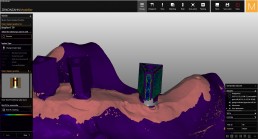
Figure 6: Comparison of the scanned Scanmarkers with the Scanmarkers’ geometries stored in the software yielded the exact implant positions in the jaw.
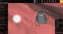
Figure 7: The emergence profile was defined before embarking on the planning phase itself.
This completed the preparations for the subsequent tooth set-up and modellation in the Zirkonzahn.Modellier software.
At the outset of the set-up process, we found that the status of the residual mandibular dentition would permit the definition of the appropriate vertical dimension. When selecting the tooth shapes, we referred to the AREUS natural tooth sets from Heroes Collection virtual tooth library (Fig. 8). This step was concluded by modelling the gingival tissues that were still missing (Fig. 9).
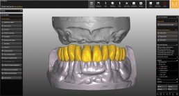
Figure 8: The digital set-up was carried out with the aid of a tooth set from the Heroes Collection virtual tooth library.
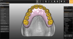
Figure 9: Digital modelling of the missing gingival aspects.
As usual, we availed ourselves of the benefits of CAD planning (as described in the introduction to this article) and produced an easily adjustable resin prototype in Temp Basic before the definitive zirconia restoration was fabricated (Fig. 10).
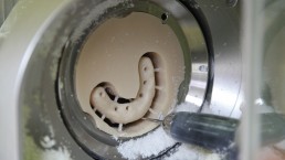
Figure 10: Implementation of the calculated strategy using one of the Zirkonzahn milling units. This example shows a restoration being milled from a Temp Basic resin block.
This resin prototype served two purposes. On the one hand, it allowed the dentist to demonstrate the appearance of the planned restoration to his patient, who in turn was able to “test-run” the restorative CAD design proposed by the dental technician in real life and to evaluate it with the practitioner in terms of function, aesthetics, phonetics etc. The insights gained helped the patient develop well-founded ideas regarding possible changes to be implemented in the definitive restoration. Following the build-up of the gingival aspect using gingival composite resins (Gingiva-Composites), the result was checked on the articulator and sent to the dentist.
After the patient had been wearing the prototype for two months (Figs. 11 and 12), it was removed from the mouth, and the few adjustments that the clinician had made were transferred to the digital data set by an additional scan. The scan data were matched with the existing CAD modulation and subsequently served as a digital wax-up for the planning of a monolithic restoration made of Prettau® Zirconia. No changes needed to be made to this wax-up in the CAD software, except that the screw access channels were adapted to the material properties of zirconia. Specifically, in order to avoid chipping and fractures at the edges of the palatal ends of the screw access channels, these edges were blunted by 0.2 mm (Fig. 13).
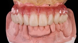
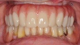
Figures 11 and 12: The prototype on the articulator and in situ (centric occlusion): The resin structure was utilised both for patient consultations and as an actual provisional. The gingiva was layered with gingival composite resins (Gingiva-Composites).
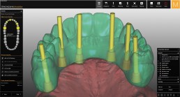
Figure 13: Making allowance for the properties of zirconia during the modulation step: blunting the edges of the screw access channels.
During the subsequent nesting in the Prettau® Zirconia blank (Fig. 14), the software automatically provided the full-arch bridge with a sintering support[1] that would later be needed during sintering to prevent structural deformities (Figs. 15 and 16). With a few clicks it was possible to align the seven connectors between the bridge and the sintering support in an optimal way, making sure to align the connectors symmetrically on the same plane. The Zirkonzahn.Nesting software then calculated the milling strategy. Following the fabrication of the restoration using the M5 Heavy Metal milling unit, the resulting zirconia structure was adjusted manually.
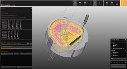
Figure 14: The Zirkonzahn.Nesting CAM software calculates the appropriate milling strategy (here: for Prettau® Zirconia).

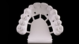
Figures 15 and 16: The digital structure and the milled structure after the milling process in a Prettau® Zirconia blank. The Zirkonzahn.Nesting software automatically provided the sintering support (to ensure distortion-free sintering) for the structure based on the system’s default settings applicable to the zirconia material.
One legal point to observe is that dimensionally accurate sintering of zirconia using a sintering support is protected by a patent granted to 3M (EP 1154969 B2) and therefore requires the user of the technology to obtain a licence. Zirkonzahn has secured this licence for its dental materials on behalf of its customers until the end of the patent term. Information on whether a valid license is available can be obtained from the manufacturer of the respective zirconia material or from the patent owner.
Despite the versatility of automated manufacturing, manual adjustment still requires the tactile acuity and the aesthetic sense of the dental technician – something that is not likely to change in the near future. It also allows last-minute individual characterisation in terms of a natural depth effect as well as an aesthetic shade and shape of the restoration.
Manual dexterity: an indispensable asset when finishing any CAD/CAM-fabricated restoration
After retrieving the milled structure from the blank, it was first manually cut back to prepare for ceramic veneering. Although Prettau® Zirconia can be successfully used to produce fully contoured restorations, this material still offers the possibility of an individual ceramic build-up, allowing the dental technician’s personal preferences to be incorporated in the final aesthetic design. For this purpose, it is sufficient to provide a thin ceramic layer in the anterior region – in the present case it was mostly limited to teeth 14 to 24, which we prepared as follows (Figs. 17 – 20):
-Corrugated vertical cut-backs in the area between the mamelons – this allowed the transparency and depth of natural teeth to be replicated by the subsequent ceramic build-up.
-Curved lines of limited depth in the central third – this provided the visual dynamics of the natural tooth anatomy.
-Fully contoured incisal edges – this was an important first processing step is to avoid chipping.[1]
-Small channels were drilled into the convex tissue surface of the structure in the areas of gingival contact to allow access for oral hygiene measures.
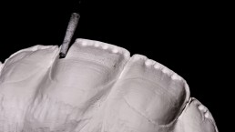
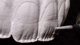
Figures 17 and 18: The manual reduction: vertical reduction, to provide transparency and depth in the areas with light-reflecting ridges and mamelon; curved lines of limited depth in the central third; fully contoured incisal edges to avoid chipping.
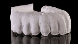
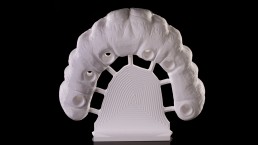
Figures 19 and 20: The reduction for the ceramic build-up was carried out mainly in the anterior region. Small channels were drilled into the convex tissue surface of the structure in the areas of gingival contact to allow access for oral hygiene measures.
Using a metal-free brush, the unsintered structure was stained with Colour Liquid Prettau® Aquarell. Of course, every dental technician will have his or her own personal preferences when it comes to staining methods and objectives. In this particular case, for example, we chose to provide a relatively prominent shade for the first dentine layer in order to counteract the bleaching effect of subsequent ceramic firing cycles. The staining was performed as follows (Figs. 21 to 23):
-Base dentine shade in the crown region: staining the incisal third with two layers of dentine, the middle third with three and the cervical third with four (representing a slightly modified 3-2-1 brush technique).
-Dentine on parts of the gingiva to simulate the shimmering through of cervical tissue through the gingiva.
-Transparency effects with Colour Liquid Prettau® Aquarell Intensiv: Characterisation of the areas between the mamelons using Incisal blue and of the mesial and distal edges and the middle third with Incisal violet.
-In the gingival area, the order of staining with Colour Liquid Prettau® Aquarell is inverted (characterisation followed by application of the dentine base):
-Staining to obtain 3D effects, for example Intensiv Orange 1 in the cervical area or Intensiv Brown 2 around the frenulum.
-Base dentine with various tissue-shade gradations.
Staining before sintering constitutes an important first step toward obtaining the desired final shade of the overall restoration. The structure was sintered in the Zirkonofen 700 Ultra-Vakuum furnace (Fig. 24). If necessary, this furnace may also be reconfigured for the sintering of a different material, Zirkonzahn Sintermetall.
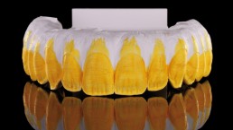
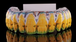
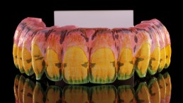
Figures 21 to 23: The colouring phase with Colour Liquid Prettau® Aquarell.
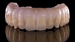
Figure 24: The Prettau® Zirconia structure after the sintering process in the Zirkonofen 700 Ultra-Vakuum furnace.
The subsequent ceramic build-up and characterisation (ICE Zirkon Ceramics and ICE Zirkon Stains 3D by Enrico Steger) initiated the second round of shade reproduction. Here was necessary to consider to transparency effects and depth but also the shape to be created. For the wash firing, the sequence was as follows (Figs 25 to 28):
-Reinforcement of the transparency effect in the incisal area between the mamelons with transparent ceramics.
-Reinforcement of the mesial and distal edges using Dynamik Dentin Blue D.
-Build-up of the interdental regions with Ceramic Transpa Neutral.
-Build-up of the remaining crown and cervical areas with Dynamik Dentin A2 D.
-Build-up of the gingiva with Ceramic Tissue 4 and Ceramic Tissue 5.
-Build-up in the palatal region with Ceramic Tissue 4 and Ceramic Tissue 5.
In the fully contoured posterior region, the characterization was carried out by applying ICE Zirkon 3D Stains by Enrico Steger to the structure.
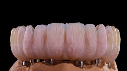
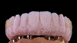
Figure 25 and 26: Ceramic build-up for wash firing.
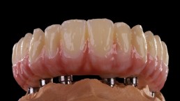
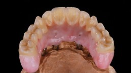
Figures 27 and 28: Result of the wash firing (vestibular and palatal).
The wash firing was followed by the dentine firing, whose main purpose is to create the anatomical shape of the individual crowns. Here the build-up consisted of (Fig. 29):
-Ceramic Dentine A2.
-Build-up of the mamelons with M1 and M2 ceramics.
-Incisal build-up using Ceramic Transpa Orange, Ceramic Transpa Blue and Ceramic Dentine A0.
-Ceramic Transpa 2 and Ceramic Transpa 3 to reinforce the transparent effect in the incisal area and in the reflection zones of the light-reflecting ridges.
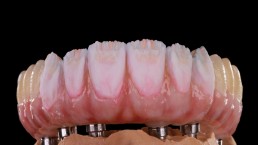
Figure 29: Ceramic build-up for dentine firing.
The dentine firing was followed by the firing of an animal ceramics to obtain the final anatomic contour while at the same time further refining the gingival aspect (Fig. 30). This in turn was followed by vertical and horizontal surface characterisation, finishing of the structure and processing of the light-reflecting ridges with rubber cups and tips. The final glaze firing sealed the surface and homogenized the entire structure (Fig. 31). The restoration was then completed with the titanium bases (anodised in golden colour to reduce the grey value of the restoration) and inserted into the patient’s mouth (Figs. 32 to 35).

Figure 30: Shaping the gingival aspect and build-up using Ceramic Enamel S1, Ceramic Enamel S2 and Ceramic Enamel S4 for the final shape.
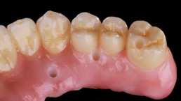
Figure 31: Part of the restoration after finishing, processing of light-reflecting ridges with rubber cups and tips and a final glaze firing.
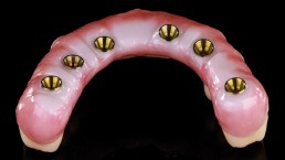
Figure 32: Structure with gold-coloured anodised titanium bases bonded after completion. The golden colour helps to reduce the grey scale value of the metal.
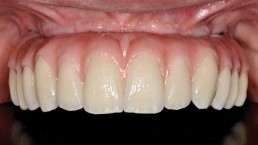
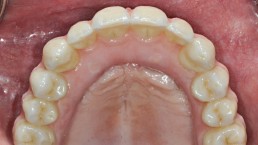
Figures 33 and 34: The finished Prettau® Bridge in situ.
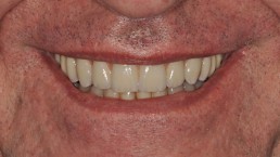
Figure 35: The new smile of the patient.
Dental technology 2.0: The pleasure of craft and technology
The combination of manual processing steps with high-precision automated production steps ensures that the profession of the dental technician stays exciting in the age of CAD/CAM. This combination reunites virtues stemming from two sources: the patience of the craftsman with the absolute accuracy of industrial production.
Over the past decades, busy hands and creative minds have perfected this workflow. All dental technicians can now draw on nearly unlimited resources!
Being in the middle of things is as much fun as it is rewarding!
All products used for this case are manufactured by Zirkonzahn. For more information, visit www.zirkonzahn.com.
[1] The long-term stability of zirconia in fixed partial restorations and the associated role of the ceramic veneer were discussed by Pihlaja et al. (2016) based on a study carried out on 102 patients between 2007 and 2010 (Pihlaja J, Näpänkangas R, Raustia A. Outcome of zirconia partial fixed dental prostheses made by predoctoral dental students: a clinical retrospective study after 3 to 7 years of clinical service. J Prosthetic Dent. 2016; 116(1): 40–46).
